
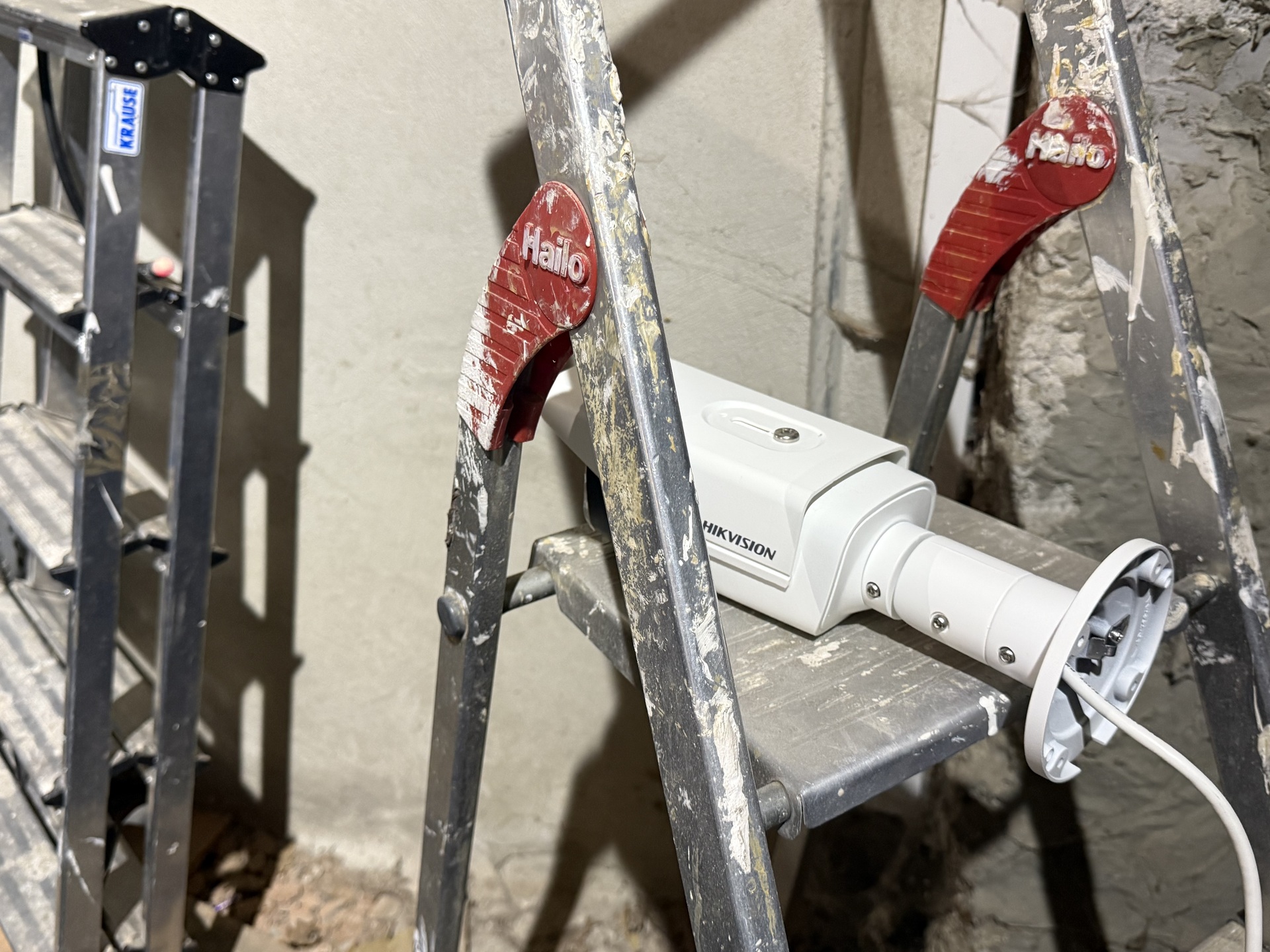
Fig. 1 Unterminated fiber illuminated by VFL and under surveillance
Fiber Optic Continuity Testing with Visible Light
After splicing an optical fiber, one should conduct a simple continuity test with visible light. For such continuity testing, one uses a visual fault locator (VFL). This device consists of a laser with a fiber optic coupler attached to its business end. Other than garden variety fiber optic transceivers that operate at 850nm or 1300nm wavelengths, this laser emits visible light - typically red light with a wavelength of 650nm. For continuity testing, one connects this laser to the freshly spliced fiber and checks whether red light is visible on the other end of the fiber run.
Laser safety: Do not look into the fiber directly!
Of course one should not look into the fiber directly - laser light can cause temporary blindness and in the worst case
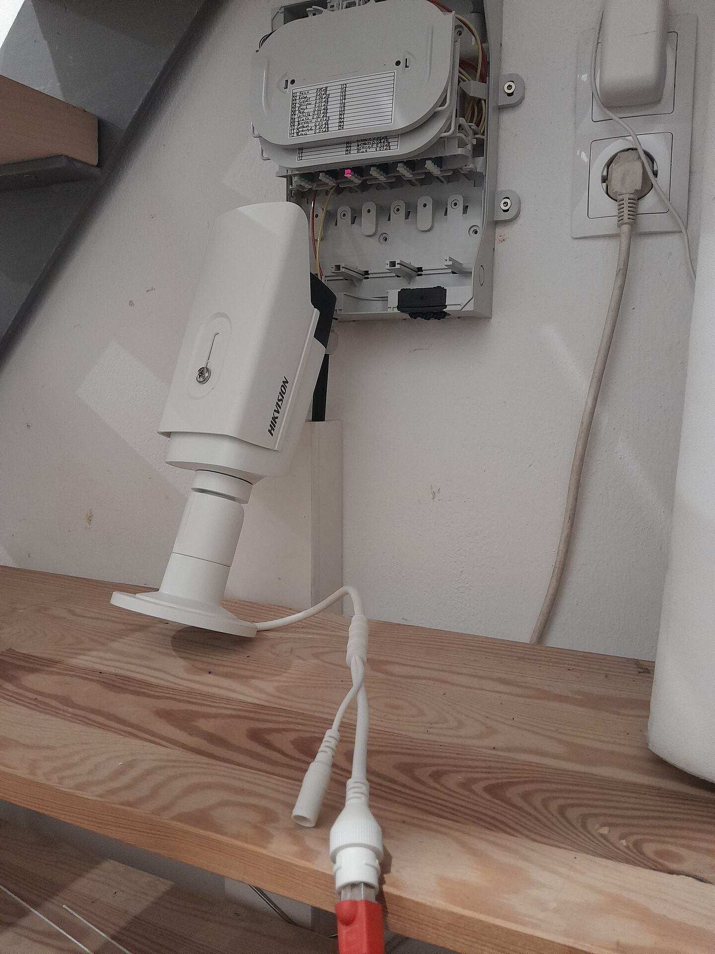
Fig. 2 Fiber coupler's dust cap illuminated by VFL and under surveillance
lasting eye damage. Instead, it's better to use a weakly reflecting projection surface such as a white sheet of paper to catch the light's reflection. Another method is covering the fiber run's end with a partially opaque material that acts as a "lamp shade" and diffuses the emitted light. One excellent object with such properties is the dust cap of a fiber optic coupler (Fig. 2). Multiple finger tips cut from a surgical glove that I'd taped over a fiber cable's open end to protect it from drawing moisture worked fine as well (Fig. 1).
Drawback: Travel Time
On the face of it, this procedure works fairly well. In practice it entails a fair amount of effort though: every time one moves the visual fault locator to a different fiber, you need to travel to the other end of the fiber run and check whether the fiber is emitting light. The time for this trip needs to be multiplied by the number of individual fibers in the cable. In the case at hand I used a loose buffer tube cable with a total of 24 fibers, so going about continuity testing in the manner just described, would have required considerable effort.
Returning the Light
In order to save time, one can return the light emitted from the fiber at the other end of the fiber run. The orthodox
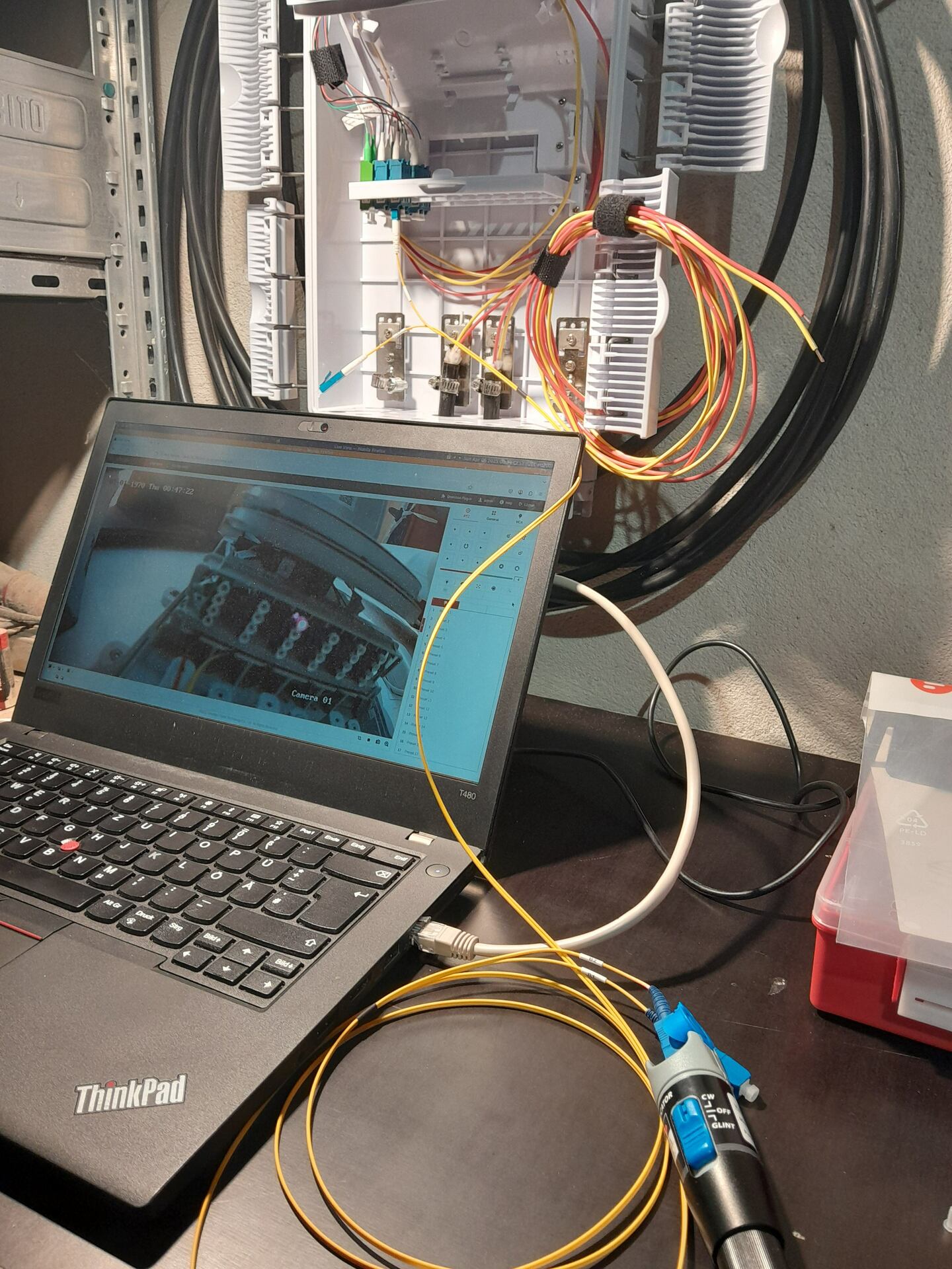
Fig. 3 Laptop screen showing the camera's view
method for accomplishing this is connecting one or more pairs of fibers in loops: on the far end, a patch cable is used to connect two fibers to each other. The visual fault locator is then connected to a member of this pair. If all is well, the light sent down the first fiber will egress from the second fiber of the pair. This method is problematic if light does not indeed return: such a loop involves a total of 4 splice connections and 8 mechanical fiber connectors. Each of these 12 connections - or even several - could be at fault. Contrast that to 2 splice connections and 4 mechanical fiber connectors for the Redneck light meter. Moreover, the loop method does not work if the fibers have only been spliced on one side of the run and you want to check continuity before moving on to splicing on the other side.
Redneck Light Meter: Indirect Light Transmission
Under certain conditions, one can avoid the problems of the orthodox method by employing an unorthodox method I dubbed the "Redneck Light Meter". This method is a bit coarse but it works well: since I also build CCTV systems I usually have one or two IP cameras around. Such a camera can be used to live stream video from the other end of the fiber run, thus indirectly transmitting the light emitted by the fiber the visual fault locator is connected to. Of course this method does not always work, since it requires network connectivity from one end of the fiber run to the other. That can be copper based LAN cabling as the one that was available in the case at hand or an Internet connection on both ends of the run. Of course it's also possible to splice a pair of fibers on either side of the run and use that to transmit the camera's video stream while splicing the remaining fibers. If any of these conditions is fulfilled, the Redneck Light Meter can be employed to quickly and effectively test freshly spliced fiber for continuity - even if the other side of the run is not spliced, yet.
Why "Redneck Light Meter"
The name derives from light meter (or more accurately, optical power meter) which is a measurement instrument for determining attentuation of fibers. The light meter is used in tandem with a light source at the same wavelength as the transceivers that will later transmit data over the fiber (e.g. 1300nm). As a first step, one calibrates the light meter by connecting it to the light source directly and measuring the intensity of the light received. This is the reference intensity. Next, one connects the light source to one end of the fiber run to be measured and measures the intensity of the light emitted on the far side of the fiber run. From the difference in these two light intensities, the light meter computes the attenuation of the fiber run. The Redneck Light Meter is not quite as precise, as denoted by the prefix "Redneck". Instead it merely yields a binary result indicating whether the fiber run has continuity at the visible wave length of 650nm.
Since the Redneck Light Meter is based on surveillance cameras that employ infrared light at 850nm for illumination in dark conditions, they could probably be used for somewhat more realistic continuity testing of multimode fiber: since multimode transceivers also use light at a 850nm wavelength for data transmission, the light emitted from a light source at this wave length should theoretically be visible to these cameras. I have not tested this yet, though. The wavelengths commonly used by singlemode transceivers (1300nm and higher) are probably not visible to commonly available surveillance cameras.